6.1. Device Selection
The first step in the design process is to select an FPGA device.
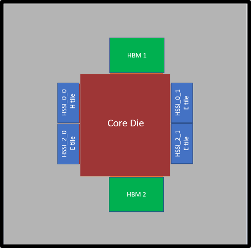
For the purpose of this example, we are using a 1SM21BE Intel® Stratix® 10 device, which has the following characteristics:
- 1 core die
- 1 H-Tile transceiver die
- 3 E-Tile transceiver dies
- 2 HBM dies
| Feature | Value | Comment |
|---|---|---|
| Family | Intel® Stratix® 10 | |
| Device | 1SM21BE | Intel® Stratix® 10 FPGA with 7 die, core fabric, H-Tile, 3 E-Tiles, 2 HBM dies. |
| Package | F55 | 55x55mm BGA package |
| Device Grade | Extended -2-smart-VID | |
| Transceiver Grade | EU1 |
Figure 7. Top View of 1SM21BE Die Layout
The following figure shows the main page of the PTC updated with device information and all other fields at default values. The power summary at the left side predicts 6.447 watts of power dissipation. This is typical static power for this device when not instantiated, and with all dies at 25°C.
If we change the power characteristics to maximum or increase the junction temperature, the power consumption also increases. For more information on these relationships, refer to the Static Power and Typical Power topic, below.
Figure 8. PTC Main Page Updated with Device Information

Note in the message window in the above figure, Typical power calculations should not be used for regulator sizing and thermal analysis. This message occurs because the Power characteristics field is set to Typical, however the PTC activates it's thermal calculation only when the Power Characteristic field is set to maximum. To calculate all thermal parameters with maximum static power, set Power characteristics to maximum.